 English
 Español
 中文
News
Home / News / Industry News / How to Size Refrigerant Piping: Practical Steps, Tables and Field Tips
Line sizing is one of those jobs that looks like a simple table lookup and turns out to be a judgment call. A run that is one size too small shows up as lost capacity on the hottest afternoon of the year, while a run that is one size too large can quietly starve a compressor of oil. After three decades of drawing copper tube for refrigeration and air-conditioning builders, we have found that the right answer usually sits between those two extremes, and that the fastest way to reach it is to work through the circuit one line at a time.
Every sizing decision in a refrigeration circuit trades three things against each other: pressure drop, oil return and installed cost. Pressure drop matters because in a refrigerant line, the pressure you lose is capacity you lose. On the suction side, a drop of roughly 2 °F (about 1 K) in saturation temperature is the conventional ceiling; on the liquid line the allowance is tighter still, often around 1 °F, because any flash gas ahead of the metering device eats into the subcooling you paid for.
Oil return sets the floor. A tube must stay small enough for the refrigerant to keep its velocity high enough to sweep compressor oil back home, and that requirement becomes hardest to meet at part load, when mass flow falls but the pipe diameter does not change.
Cost and material set the ceiling. Larger tube means more copper, more insulation, more support and more refrigerant charge. Because all three forces pull in different directions, no single table ever answers the question on its own. A sizing table gives you a starting diameter; the rest of the work is verification.
The suction line carries the largest volume of the lowest-density gas in the system, which is why it is normally the biggest tube in the circuit. It is also the line where the two constraints collide most visibly: you want a generous diameter for pressure drop, yet you need velocity for oil return. Check both full load and minimum load. Where the load swings widely, a reduced-diameter riser, or a double riser that drops one branch out at low load, is a common and sensible compromise.
 TP2 Refrigeration Copper Tube, 12–28 mm ODHigh-purity TP2 copper tube for HVAC and refrigeration main lines, balancing strength, formability, corrosion resistance and efficient refrigerant circulation.View Product →
Liquid lines are small because liquid refrigerant is dense and moves little gas volume. The design goal here is different: keep the refrigerant liquid. Excessive pressure drop, a long vertical lift without enough subcooling, or a line routed through a hot space can all produce flash gas at the expansion valve, and the symptom looks exactly like an undersized line even when the diameter was calculated correctly.
The hot gas line is sized much like the suction line, with the same velocity considerations, but pressure drop here costs compressor power directly and raises the discharge temperature. Horizontal runs and vertical risers both need to carry oil, and the pipe should be pitched in the direction of flow wherever the layout allows it.
Short branch lines and header connections are usually governed by the fitting sizes available rather than by the sizing table. Keep transitions gradual, avoid unnecessary reducers, and remember that every elbow adds to the equivalent length you will use in the calculation.
The sequence below is the one we recommend to fabricators and installing contractors who want a repeatable result rather than a guess.
The numbers below are the rules of thumb we see most often in manufacturer manuals and design guides. Treat them as a sanity check on your calculation, never as a replacement for it.
| Line type | Typical velocity range | Common design limit | What goes wrong |
|---|---|---|---|
| Suction, horizontal | 700–1,500 ft/min (3.5–7.5 m/s) | About 2 °F (1 K) saturation drop | Oversizing stops oil return |
| Suction, riser | 1,000–2,000 ft/min upward | Same overall drop limit | Upsizing the riser with the run |
| Liquid | 200–500 ft/min | About 1 °F (0.5 K) drop | Flash gas and lost subcooling |
| Discharge | 1,500–3,000 ft/min | 1–2 °F drop | High discharge temperature and power draw |
Most of the sizing errors we hear about are not pressure drop errors at all; they are oil return errors. Compressor oil leaves with the discharge gas, travels the circuit and has to find its way back through the suction line. At full load the velocity is usually generous. At 30 percent capacity on a mild day, the same tube may see a fraction of the mass flow, and the oil simply pools in the lowest point of the run.
This is why sizing is done twice, at maximum and minimum load. Horizontal suction runs are commonly held to a minimum in the region of 500 ft/min, with vertical risers set considerably higher so oil can be lifted against gravity. Where a system spends long periods at low load, a double riser, an oil separator, or a smaller riser with an inverted trap at the base are all practical answers. Whatever you choose, keep the suction line as short and as direct as the layout permits, because every extra metre of pipe is another place for oil to settle.
There is a natural instinct to add a size for safety. In refrigerant piping that instinct usually backfires. The symptoms of a line that is too large are easy to recognise once you know them:
Undersizing has its own signature: high superheat, a whistling or roaring line, elevated discharge temperature, and a compressor working harder than its rating suggests. Both faults are avoidable with the same two load checks.
Once the diameters are settled, the tube selection is straightforward but worth doing deliberately. Refrigeration work calls for clean, capped ACR-grade copper in a deoxidised grade such as C12200, supplied to a recognised standard. Material that conforms to ASTM B280 requirements is the usual specification for air-conditioning and refrigeration service, and projects in other markets may call for EN 12735 or JIS H3300 instead.
Temper matters as much as grade. Hard-drawn tube holds a straight run neatly and supports its own weight over long spans, while annealed pancake coil bends easily by hand and reduces the number of brazed joints in a congested plant room. For field-built split systems, ACR copper pipe supplied clean and capped saves a great deal of nitrogen purging and rework on site.
 Small-Diameter TP2 Copper Tube, 5–12 mm ODFlexible TP2 copper tubing for appliance, instrument and heat-exchanger lines, easy to bend, cut and weld in compact installations.View Product →
Small-bore tube covers the liquid lines and capillary connections where pressure drop budgets are tight and dimensional consistency matters. Large-bore tube handles the suction and discharge runs of bigger packaged and VRF systems, where a fraction of a millimetre in wall thickness changes both the weight and the working pressure rating.
 Custom Large Copper Tube, 28–54 mm ODCustom large copper tube for high-pressure industrial piping, heat exchangers and power-plant systems, offering corrosion resistance and thermal conductivity.View Product →
Sizing refrigerant piping rewards a little patience. Decide the allowable drop, choose the diameter, then test it again at the lowest load the system will actually see. Do that and most commissioning problems disappear before the first gauge is connected. If you are working through a project and want to talk through diameters, tempers or standards with people who have spent years on the mill floor, our team is always glad to help.
Standard refrigeration copper tube with an outer diameter of 12-28mm is made of high-quality TP2 copper (C12200/DHP), specifically designed for HVAC s...
See Details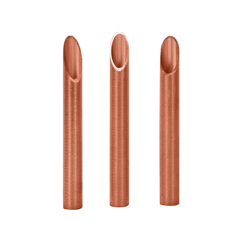
The copper evaporator tube adopts a unique fin design, and the external fins are equipped with specially designed interconnected channels, so that eac...
See Details
 Tangpu Industrial Zone, Shangyu District, Shaoxing City, Zhejiang Province, China
 +86-13567501345
© Zhejiang Jingliang Copper-Tube Products Co., Ltd All rights reserved.

